Today, we build us an animated and programmable mood lamp that can be nicely used as a functional decoration. This tutorial is understood only as a suggestion, especially the design of course is always in the eye of the beholder.
 and a digital RGB LED Strip (5050 LEDs with WS2811 controller) - unfortunately, the beautiful color effect is not so good to see in the photo")
Mood lamp with an Olimexino-32U4 (Arduino Leonardo compatible) and a digital RGB LED Strip (5050 LEDs with WS2811 controller) – unfortunately, the beautiful color effect is not so good to see in the photo
First, we must make some errands, materials used can be found at the end of the article.
Instructions for the mood light:
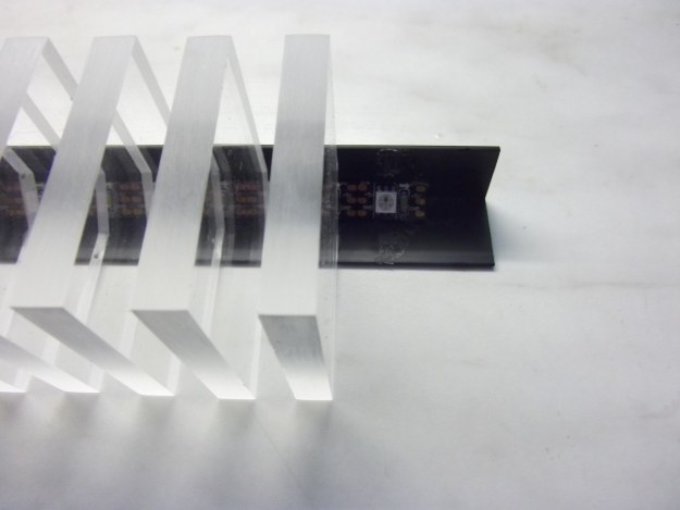
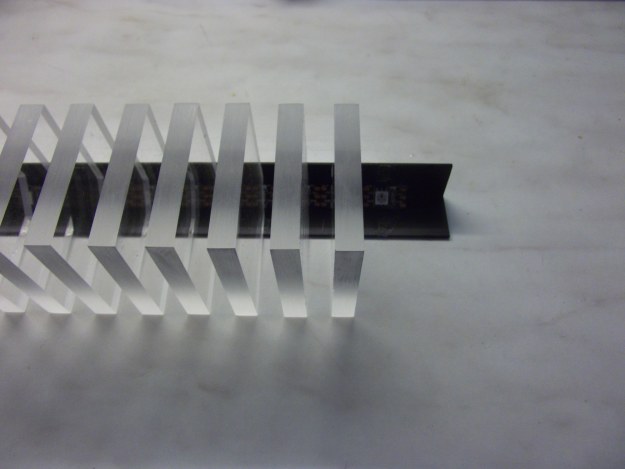
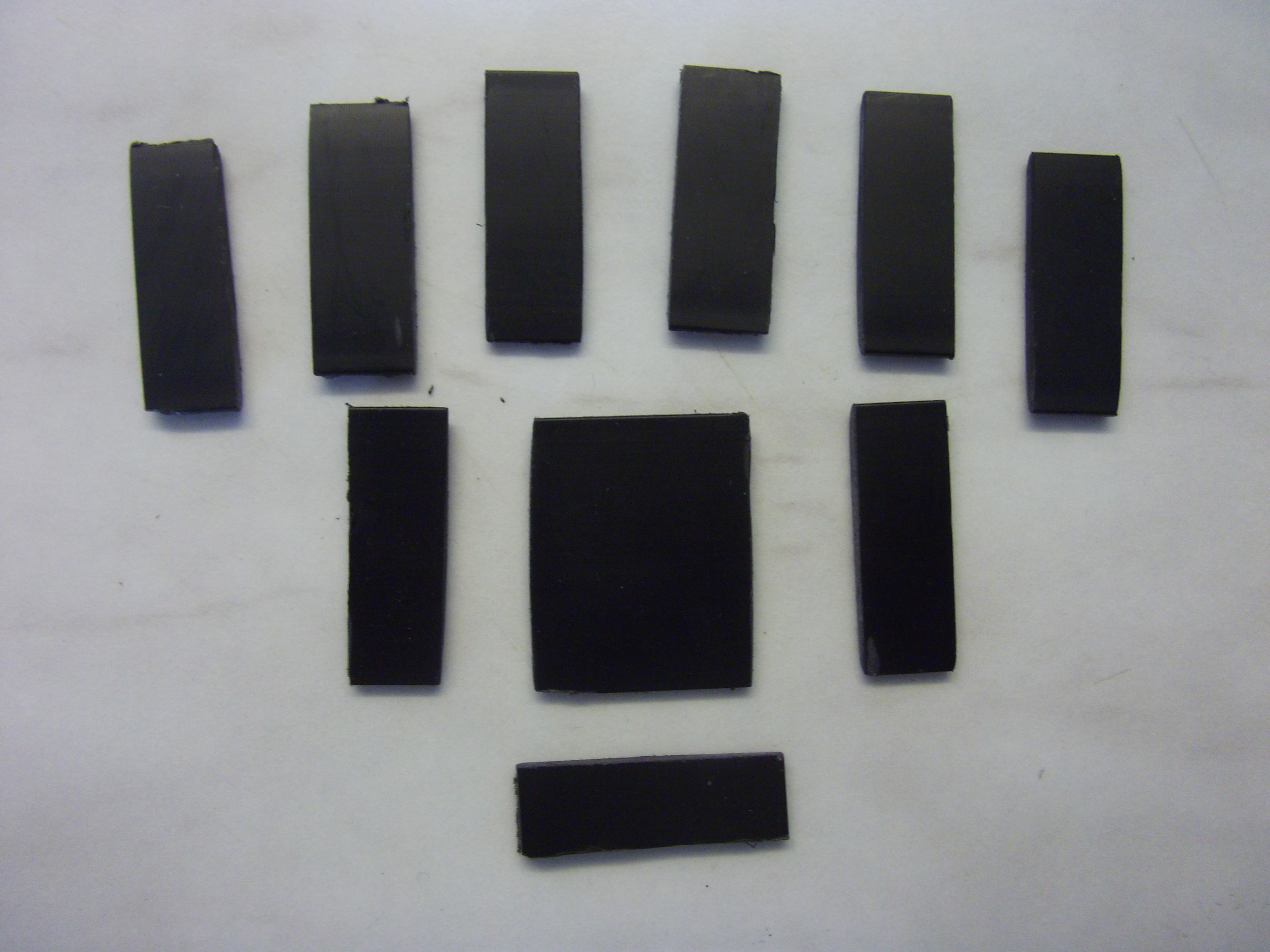
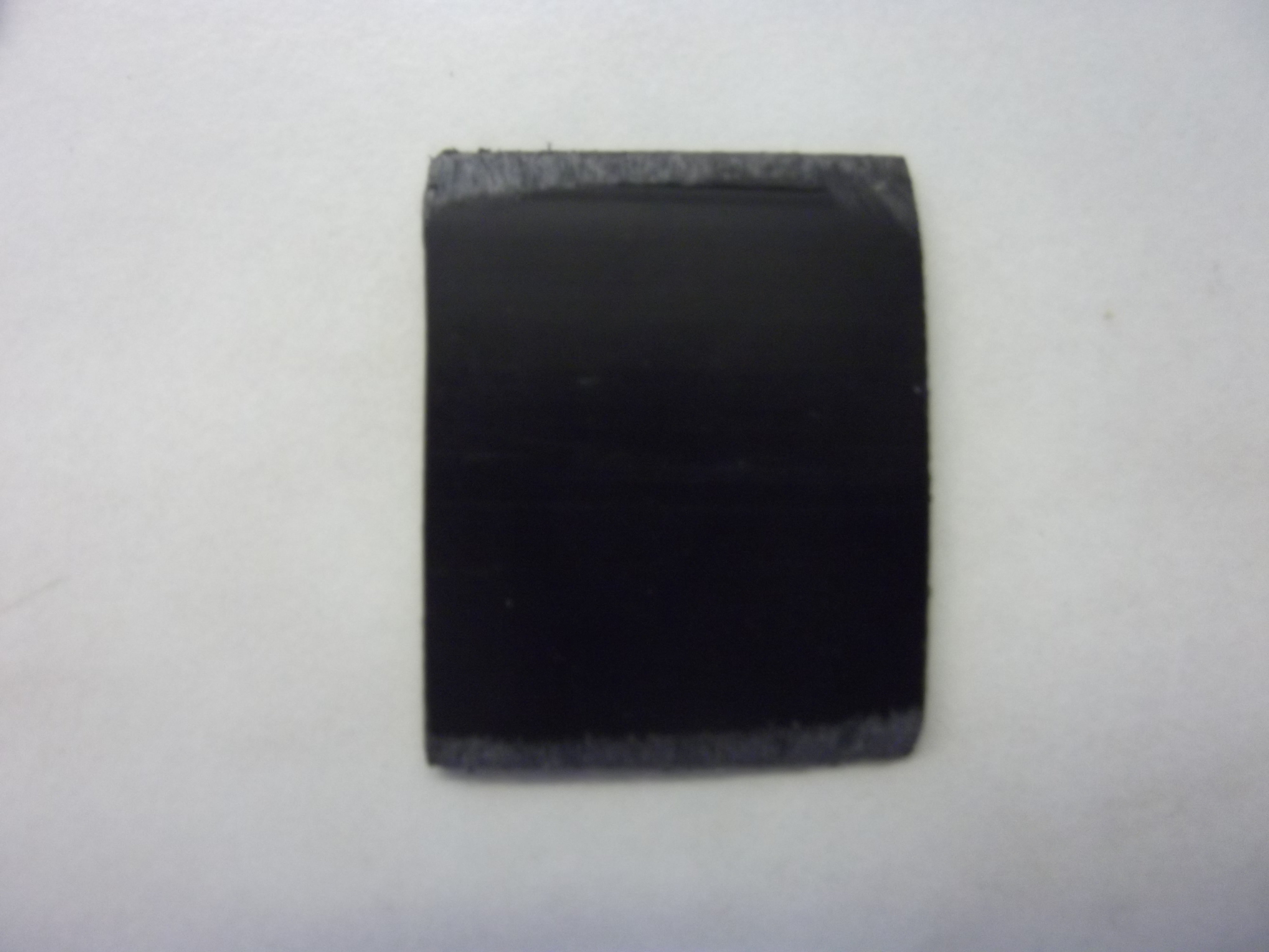
The LED RGB strip has a distance of about 16mm between the LEDs. For a symmetrical arrangement acrylic sheets of 8mm thickness are the best way. We use 10 pre-cut transparent acrylic glass sheets (Plexiglas) with dimensions of 50mm x 50mm x 8mm.


With a Dremel and a cutting wheel or a saw we cut a triangle from the edge (about 10mm at the isosceles sides), but without removing the protective film before. Then all 5 edges of acrylic plates must be thoroughly sanded with fine sandpaper. Possibly sand it with 40, then 80 grit – if the edges are rough and uneven – then edit the sides with a fine 120 grit.


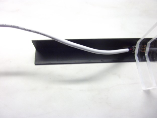
Next, we put the black plastic profile (L, 90 ° right angle, approx 20mm x 20mm) to a length of about 250mm. This goes again with a Dremel and a cutting wheel or a saw.
Now glue the acrylic glass in the plastic profile. May you can fix the strip before with glue. A black cable makes by the way, not like in the example, probably more sense.
For the ground plate we use an acrylic sheet in black (size approx 140mm x 100mm x 10mm). A thickness of at least 10mm is recommended to give enough stability to the lamp. We draw here a triangle, which has the dimensions of L-section, which is to be inserted later there.There we drill 3 holes at the corners of the triangle and then cut using a fretsaw the slots on the 2 sides. (In absence of a fretsaw was the example a little fudged and used a Dremel and cutting disc.) A small corner is subsequently sawed or filed for cable management.
We stick 4 rubber feet under the base plate and then plug the profile, including cable, into or through the plate.

Now we cut covers for the foot, above and between the acrylic plates, because the LED strip and the cable are better concealed then. (Must not be made if the technology is to be shown.) The adhesive on the back edges of the covers we grind for a better grip, with a 45 ° angle slightly and then glue carefully all the covers.
However, it is better to make a functional test before (schematic and code below).

Wiring:
Now we connect the LED Strip (where we had the cable already soldered) with the Arduino and the power supply:
| Arduino (Uno, Nano, Pro Mini, Leonardo, Olimexino 32U4) |
RGB-Strip (WS2811) |
Power source 5V (minimum 500mA or more) |
| VCC | 5V+ | VCC 5V |
| GND | GND | GND |
| D12 | DIN |

 with breadboard, power supply and wiring to the WS2811 RGB LED Strip")
Attention, do not power the circuit from the Arduino power source. An external 5V power source is needed.
Source code (Sketch):
Before uploading the sketch to the Arduino, we still need to install the FastSPI_LED2 library.
The following sketch includes a simple animated rainbow color spectrum with different random velocities, brightness levels and changes of direction.
#include "FastSPI_LED2.h"

#define NUM_LEDS 10  // Anzahl der LEDs im Strip

struct CRGB { byte g; byte r; byte b; };
struct CRGB leds[NUM_LEDS];

WS2811Controller800Mhz<12> LED;  // Strip an Pin D12


void setup() {
  LED.init();
}

CRGB rgb;

void loop() {

 randomSeed(millis());

 int wait=random(1,30);
 int dim=random(4,6);
 int max_cycles=8;
 int cycles=random(1,max_cycles+1);

 rainbowCycle(wait,cycles,dim);

}

void rainbowCycle(uint8_t wait,byte cycle,byte dim) {

  int cycles, j, k;

  for(cycles=0;cycles<cycle;cycles++){

    byte dir=random(0,2);
    k=255;

    for (j=0; j < 256; j++,k--) {     // cycles of all 25 colors in the wheel

      if(k<0)k=255;

      for(int i=0; i<NUM_LEDS; i+=1) {

        Wheel(((i * 256 / NUM_LEDS) + (dir==0?j:k)) % 256,dim);
        leds[i]=rgb;
      }
      LED.showRGB((byte*)leds, NUM_LEDS);;
      delay(wait);
    }
  }
}

void Wheel(byte WheelPos,byte dim){

  if (WheelPos < 85) {
   rgb.r=0;
   rgb.g=WheelPos * 3/dim;
   rgb.b=(255 - WheelPos * 3)/dim;;
   return;
  }
  else if (WheelPos < 170) {
   WheelPos -= 85;
   rgb.r=WheelPos * 3/dim;
   rgb.g=(255 - WheelPos * 3)/dim;
   rgb.b=0;
   return;
  }
  else {
   WheelPos -= 170;
   rgb.r=(255 - WheelPos * 3)/dim;
   rgb.g=0;
   rgb.b=WheelPos * 3/dim;
   return;
  }
}
Download Source Code (WS2811_Rainbow.ino)
Short video with an animated rainbow color gradient in the dark (with changing ambient light levels):
Other suggestions:
- an Arduino Pro Mini or Nano could be built directly under the foot, also a standard connection for a 5V power supply
- different light effects
- other shapes or sizes of the acrylic glass sheets
- Microphone or line-in for sound detection
(for example music)
Shopping:
Some components may require, and we should be purchased directly at the hardware store, such as the plastic profile (20mm x 20mm x 250mm).
Acrylic sheets for the LEDs: 10 sheets 50mm x 50mm x 8mm transparent, plus ground plate approx 140mm x 100mm x 10mm black.
In this tutorial, a section with 10 LEDs is used, from a strip with 60 LEDs per meter. Beware, there are also strips with, for example, only 30 LEDs / m, do not buy these.
An additional power supply is required, either here as a breadboard module or just a normal 5V power supply with at least 500mA.
Components:
Good?
 Deutsch
 English