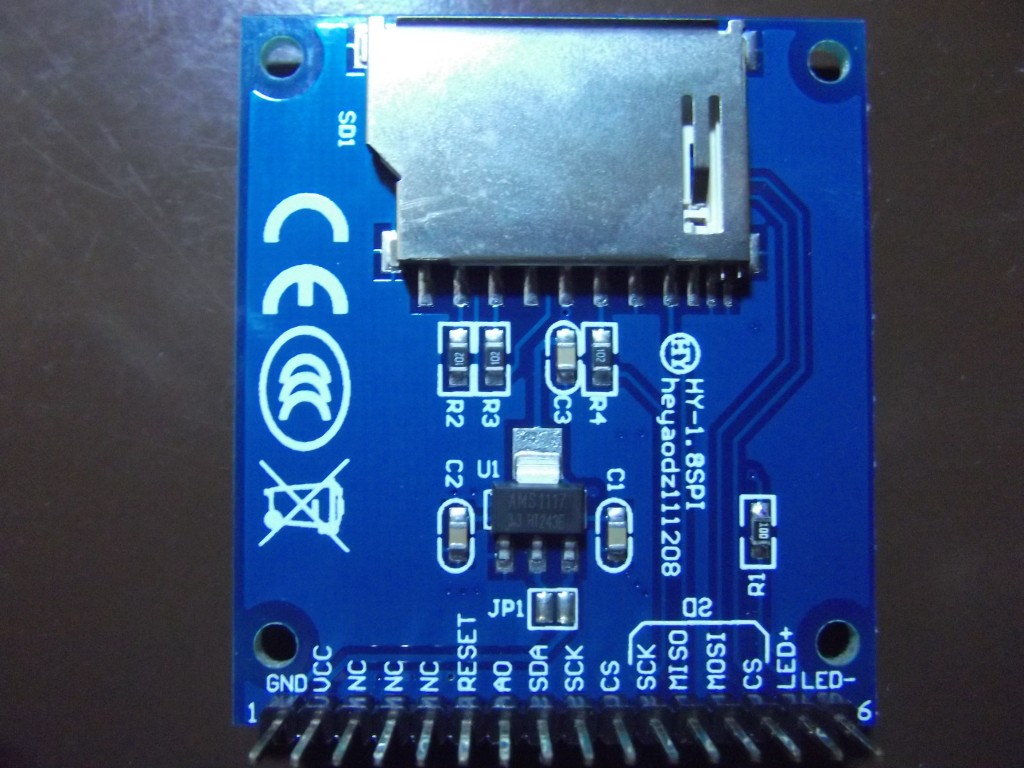
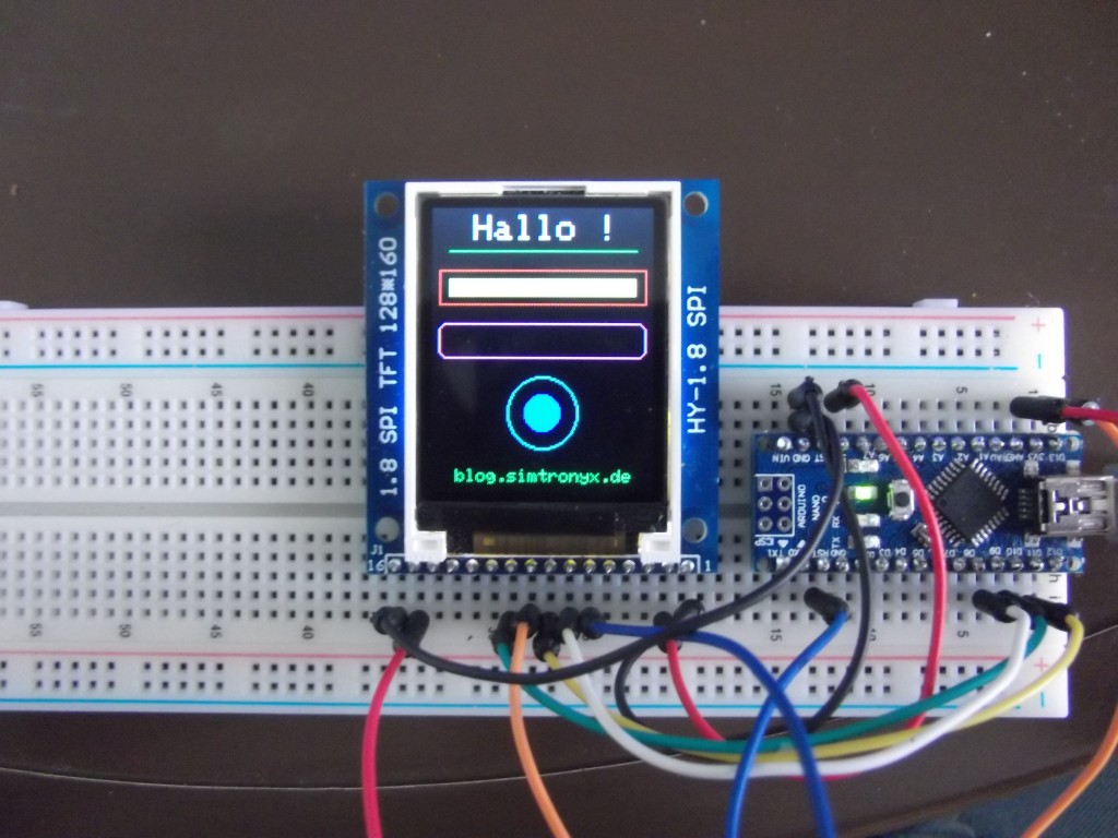
To give our Arduino the chance to tell sometimes what’s actually going on and do not always use the serial monitor, it is time to buy him a small display. Fortunately, there is a wide range of available shields and breakout boards. In this case, we use a 1.8 inch TFT color display with 128×160 pixels (HY-1.8 SPI, the name on the board), equipped with an SPI interface, which gives us the opportunity compared to displays with parallel interface, to have more free ports for other applications available.
Through the – in comparison to a pure character display – high resolution, we also have enough space to display various information about the status of our programs/circuits.
But now we continue with the practical part and wiring the display to the Arduino, in this case an Arduino Nano, which can be replaced by an other Arduino type. So we connect the pins as shown in the table below.
Schematic (Arduino wiring of the HY-1.8 SPI TFT display):
| Arduino (Mini, Nano, Uno) | HY-1.8 SPI |
| D9 | Pin 07 (A0) |
| D10 (SS) | Pin 10 (CS) |
| D11 (MOSI) | Pin 08 (SDA) |
| D13 (SCK) | Pin 09 (SCK) |
| D8 | Pin 06 (RESET) |
| 5V (VCC) | Pin 02 (VCC) |
| GND | Pin 01 (GND) |
| 3.3V or 5V (VCC) | Pin 15 (LED+) |
| GND | Pin 16 (LED-) |

Pinout of the 1.8 inch TFT color display (back side)
Source code (sketch):
Now we need to download 2 libraries to control the display. This would on the one hand the Adafruit library for controlling the display chipset (ST7735) and also a ”graphics. After we have added them to the Arduino libraries, we upload the following sketch to our Arduino:
// Grafiktest 1.8 Zoll TFT-Farb-Display (HY-1.8 SPI)

#define TFT_PIN_CS   10 // Arduino-Pin an Display CS
#define TFT_PIN_DC   9  // Arduino-Pin an
#define TFT_PIN_RST  8  // Arduino Reset-Pin

#include <SPI.h>
#include <Adafruit_GFX.h>    // Adafruit Grafik-Bibliothek
#include <Adafruit_ST7735.h> // Adafruit ST7735-Bibliothek

Adafruit_ST7735 tft = Adafruit_ST7735(TFT_PIN_CS, TFT_PIN_DC, TFT_PIN_RST);  // Display-Bibliothek Setup

void setup(void) {

  tft.initR(INITR_BLACKTAB);   // ST7735-Chip initialisieren

}

void loop() {

  // Bildschirm mit Farbe fuellen
  // fillScreen(farbe);
  tft.fillScreen(ST7735_BLACK);

  delay(2000); // 2 Sekunden warten

  // Fontgroesse setzen
  // setTextSize(groesse);
  tft.setTextSize(2);

  // Schrift umbrechen?
  // setTextWrap(true);   true=Ja, false=Nein
  tft.setTextWrap(true);

  // Textposition setzen
  // setCursor(x,y);
  tft.setCursor(24,4);

  // Textfarbe setzen
  // setTextColor(farbe);
  tft.setTextColor(ST7735_WHITE);

  // Text ausgeben
  // print(text);
  tft.print("Hallo !");

  delay(2000); // 2 Sekunden warten

  // Linie zeichnen
  // drawLine(x_start,y_start,x_ende,y_ende,farbe);
  tft.drawLine(10,24,118,24,ST7735_GREEN);

  delay(2000); // 2 Sekunden warten

  // Ein Rechteck zeichnen
  // drawRect(x_oben_links,y_oben_links,weite,hoehe,farbe);
  tft.drawRect(4,35,120,20,ST7735_RED);

  delay(2000); // 2 Sekunden warten

  // Ein gefuelltes Rechteck zeichnen
  // drawRect(x_oben_links,y_oben_links,weite,hoehe,farbe);
  tft.fillRect(10,40,108,10,ST7735_YELLOW);

  delay(2000); // 2 Sekunden warten

  // Ein Rechteck zeichnen
  // drawRoundRect(x_oben_links,y_oben_links,weite,hoehe,rundung,farbe);
  tft.drawRoundRect(4,65,120,20,5,ST7735_MAGENTA);

  delay(2000);

  // Einen Kreis zeichnen
  // drawCircle(x_oben_links,y_oben_links,radius,farbe);
  tft.drawCircle(64,115, 20, ST7735_CYAN);

  delay(2000); // 2 Sekunden warten

  // Einen gefuellten Kreis zeichnen
  // fillCircle(x_oben_links,y_oben_links,radius,farbe);
  tft.fillCircle(64,115, 10, ST7735_BLUE);

  delay(2000); // 2 Sekunden warten

  // Neue Fontgroesse setzen
  // setTextSize(groesse);
  tft.setTextSize(1);

  // Neue Textfarbe setzen
  // setTextColor(farbe);
  tft.setTextColor(ST7735_GREEN);

  // Neue Textposition setzen
  // setCursor(x,y);
  tft.setCursor(14,147);

  // Text ausgeben
  // print(text);
  tft.print("blog.simtronyx.de");

  delay(8000); // 8 Sekunden warten

  // Gesamtes Display invertieren?
  // invertDisplay(true);   true=Ja, false=Nein
  tft.invertDisplay(true);

  delay(1000); // 1 Sekunde warten

  // Gesamtes Display invertieren?
  // invertDisplay(false);   true=Ja, false=Nein
  tft.invertDisplay(false);

  delay(1000); // 1 Sekunde warten
}
…and now the display is running.
Some blog visitors and hobbyists have occurred an error during compilation. This error came from the “Robot_Control” library, which is may not compatible with the used libraries. The “Robot_Control” library should then be temporarily removed.
Similar or postgraduate projects:
Components:
| eBay: | 1.8 inch TFT SPI display Breadboard jumper wires |
| Amazon: | Breadboard jumper wires |
Good?

 Deutsch
 English