To be a little entertained when tinkering, we build us today a small FM stereo radio using a slightly older, but extremely inexpensive, TEA5767 breakout board. However, by this time it will be a little more complicated because we need to solder and have to build some adapters.
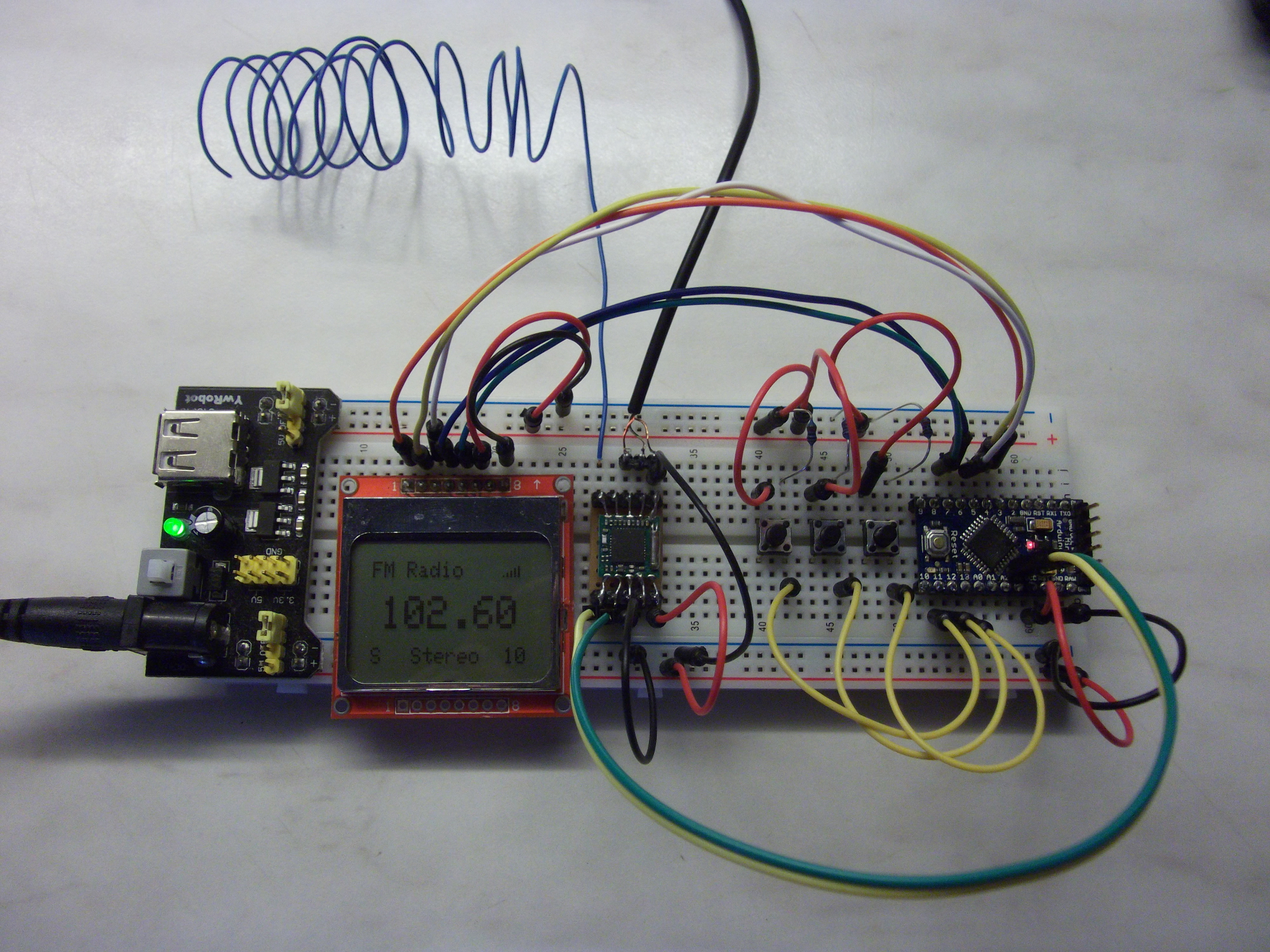
FM stereo radio TEA5767 module and an Arduino
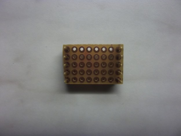
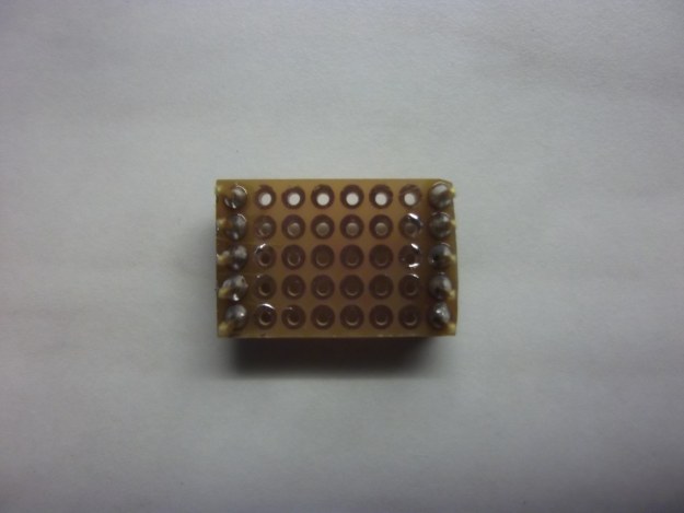
First, we build ourselves an adapter for the TEA5767. We take a matrix board, which we cut like in the following picture:


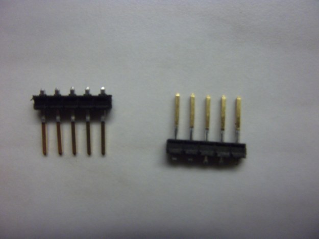
Then we edit two 5 pin headers where we push in the pins so far that they project about 1mm above and tin these with solder:
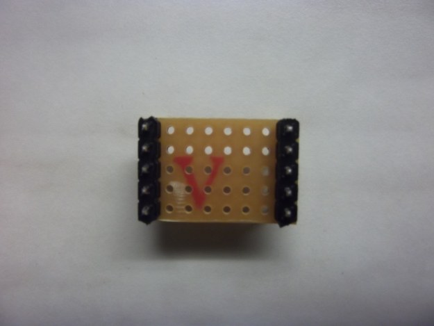
Now we put the headers on the finished prototype PCB and solder them firmly:
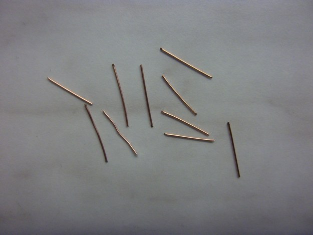
Then we take a little jumper wire, remove the insulation and cut us 10 about 1cm long pieces. (Alternatively you can take the legs, for example, from resistors, LEDs, etc..)
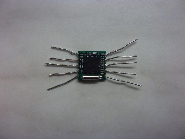
Now we tin the wires and solder the wires to the breakout module:
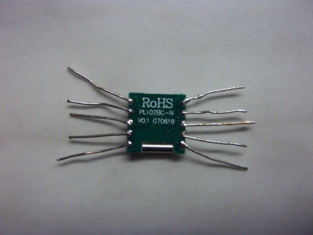
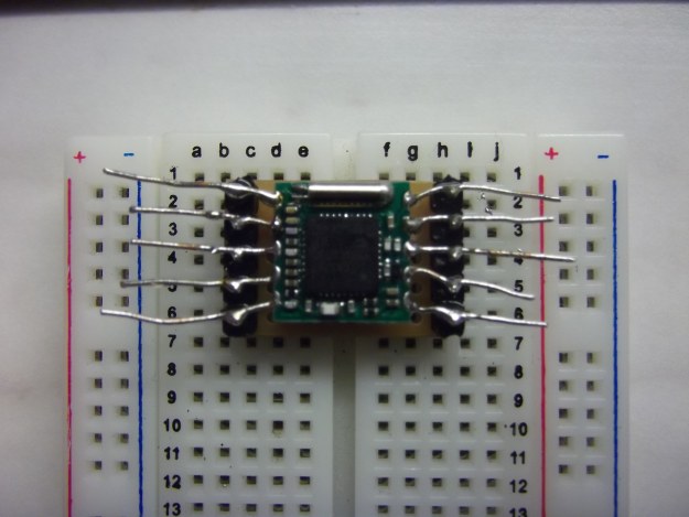
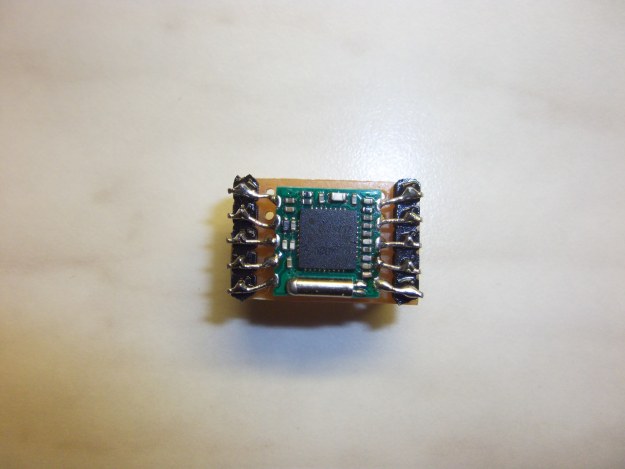
Once this is done we put the board on our prepared hole matrix adapter (best put on a breadboard) and solder everything. We must proceed relatively quickly, however, as otherwise may the wires get off from the FM module. (You may resolder again.) Still cutting off the protruding wires and now have our TEA5767 breadboard adapter module ready:

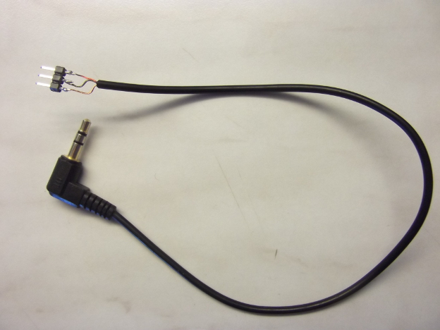
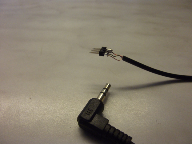
As the radio module has a line-out output, we preparea breadboard cable adapter. This can of course also be a RCA or a stereao-jack. This is another header (3-pin) soldered with an audio cable of your choice. In general, is white the left channel, red the right channel and the compound is black.
Now the TEA5767, the display, the Arduino and power supply are wired according to the following table:
| Arduino (Pro Mini 3,3V, Olimexino-32U4 3,3V mode!) |
TEA5767-Modul | Nokia 5110 LCD | Power (Breadboard power module) |
| ANT Antenne RF | |||
| LEFT Audio line out left | |||
| RIGHT Audio line out right | |||
| GND | BUSMODE for I²C-Mode connect to GND | ||
| A4 (SDA) | DATA | ||
| A5 (SCL) | CLOCK | ||
| D3 | RST | ||
| D4 | CE | ||
| D5 | DC | ||
| D6 | DIN | ||
| D7 | CLK | ||
| VCC | VCC | VCC | VCC 3,3V |
| GND | GND | GND | GND |
| LIGHT optional | VCC 3,3V |

")
Caution on wiring of the LCD display.. Maybe some modules may have a different pin assignment!!
More information about the connection of the display can be found in this post: Nokia 5110 LCD, an Arduino Pro Mini 3.3V with 8MHz clock frequency (in this blog).
Also the audio adpater cable pin header is still plugged in (audio line-out according to the table above) and then we connect the buttons and the 10KOhm resistors to control the Arduino as follows:
The antenna can be a 1m long wire. For me it was without even better because the antenna has strangely fabricated noise.
Source code (sketch):
For the display 2 additional libraries must be installed:
- Adafruit PCD8544-Library (display driver)
- Adafruit Grafik-Library (graphical output)
Now just upload the sketch to the Arduino and we can start:
// TEA5767 und Nokia 5110 LCD Display

#include <SPI.h>

#include <Adafruit_GFX.h>
#include <Adafruit_PCD8544.h>

// D7 - Serial clock out (CLK oder SCLK)
// D6 - Serial data out (DIN)
// D5 - Data/Command select (DC oder D/C)
// D4 - LCD chip select (CE oder CS)
// D3 - LCD reset (RST)
Adafruit_PCD8544 lcd = Adafruit_PCD8544(7, 6, 5, 4, 3);

#include <Wire.h>

#define button_frequency_up     13
#define button_frequency_down   12
#define button_mute             11

#define TEA5767_mute_left_right  0x06
#define TEA5767_MUTE_FULL        0x80
#define TEA5767_ADC_LEVEL_MASK   0xF0
#define TEA5767_STEREO_MASK      0x80


int old_frequency=-1;
int frequency=10260;

byte old_stereo=0;
byte stereo=1;

byte old_mute=1;
byte mute=0;

byte old_signal_level=1;
byte signal_level=0;

unsigned long last_pressed;

void setup(void) {

  pinMode(button_frequency_up, INPUT);
  pinMode(button_frequency_down, INPUT);
  pinMode(button_mute, INPUT);

  Wire.begin();

  TEA5767_set_frequency();

  lcd.begin();
  lcd.setContrast(60);
  lcd.clearDisplay();

  set_text(1,2,"FM Radio",BLACK,1);
  //set_text(14,147,"blog.simtronyx.de",BLACK,1);

}


void loop() {

    if(frequency!=old_frequency){
      set_text(old_frequency>=10000?6:14,17,value_to_string(old_frequency),WHITE,2);
      set_text(frequency>=10000?6:14,17,value_to_string(frequency),BLACK,2);
      old_frequency=frequency;
    }

    TEA5767_read_data();

    if(old_stereo!=stereo){
        set_text(old_stereo?22:28,39,old_stereo?"Stereo":"Mono",WHITE,1);
        set_text(stereo?22:28,39,stereo?"Stereo":"Mono",BLACK,1);
        old_stereo=stereo;
    }

    if(old_signal_level!=signal_level){
        set_text(old_signal_level<10?76:70,39,String((int)old_signal_level),WHITE,1);
        set_text(signal_level<10?76:70,39,String((int)signal_level),BLACK,1);
        old_signal_level=signal_level;
        show_signal_level(signal_level);
    }

    if(old_mute!=mute){
        set_text(1,39,old_mute?"M":"S",WHITE,1);
        set_text(1,39,mute?"M":"S",BLACK,1);
        old_mute=mute;
    }

    delay(50);


  if(digitalRead(button_frequency_down)==HIGH){

    frequency=frequency-5;
    if(frequency<8750)frequency=10800;
    TEA5767_set_frequency();
  }
  if(digitalRead(button_frequency_up)==HIGH){

    frequency=frequency+5;
    if(frequency>10800)frequency=8750;
    TEA5767_set_frequency();
  }

  if(digitalRead(button_mute)==HIGH){

    TEA5767_mute();
  }

  delay(50);

}

unsigned char frequencyH = 0;
unsigned char frequencyL = 0;

unsigned int frequencyB;

unsigned char TEA5767_buffer[5]={0x00,0x00,0xB0,0x10,0x00};

void TEA5767_write_data(byte data_size){

  delay(50);

  Wire.beginTransmission(0x60);

  for(byte i=0;i<data_size;i++)
    Wire.write(TEA5767_buffer[i]);

  Wire.endTransmission();

  delay(50);
}

void TEA5767_mute(){

  if(!mute){
    mute = 1;
    TEA5767_buffer[0] |= TEA5767_MUTE_FULL;
    TEA5767_write_data(2);
//    TEA5767_buffer[0] &= ~TEA5767_mute;
//    TEA5767_buffer[2] |= TEA5767_mute_left_right;
  }
  else{
    mute = 0;
    TEA5767_buffer[0] &= ~TEA5767_MUTE_FULL;
    TEA5767_write_data(2);
//    TEA5767_buffer[0] |= TEA5767_mute;
//    TEA5767_buffer[2] &= ~TEA5767_mute_left_right;
  }

//  TEA5767_write_data(3);
}

void TEA5767_set_frequency()
{
  frequencyB = 4 * (frequency * 10000 + 225000) / 32768;
  TEA5767_buffer[0] = frequencyB >> 8;
  if(mute)TEA5767_buffer[0] |= TEA5767_MUTE_FULL;
  TEA5767_buffer[1] = frequencyB & 0XFF;

  TEA5767_write_data(5);
}

int TEA5767_read_data() {

  unsigned char buf[5];
  memset (buf, 0, 5);

  Wire.requestFrom (0x60, 5);

  if (Wire.available ()) {
    for (int i = 0; i < 5; i++) {
      buf[i] = Wire.read ();
    }

    stereo = (buf[2] & TEA5767_STEREO_MASK)?1:0;
    signal_level = ((buf[3] & TEA5767_ADC_LEVEL_MASK) >> 4);

    return 1;
  }
  else return 0;
}

void show_signal_level(int level){

  byte xs=68;
  byte ys=8;
  for(int i=0;i<15;i++){
    if(i%2!=0)lcd.drawLine(xs+i,ys,xs+i,ys-i/2,level>=i?BLACK:WHITE);
  }
}

void set_text(int x,int y,String text,int color,int textsize){

  lcd.setTextSize(textsize);
  lcd.setTextColor(color);
  lcd.setCursor(x,y);
  lcd.println(text);
  lcd.display();
}


String value_to_string(int value){

  String value_string = String(value / 100);
  value_string = value_string + '.' + ((value%100<10)?"0":"") + (value % 100);
  return value_string;
}
The functions of the buttons from left to right:
- Mute – sound on or off
- Frequency down by 0.05MHz
- Frequency up by 0.05MHz
The mono / stereo display is automatic, but is unfortunately on “mute” always shown as mono. Bottom left, there are two modes, “S” is “sound on” and “M” is “mute”. Bottom right is the signal strength as a number (0-15), this is still graphically displayed on the top right corner. In the middle of the screen, of course, is the actual frequency.
Have fun listening to the radio!
Components:
Good?
 Deutsch
 English